|
 |
VK5ZVS |
|
| Projects 'n' Stuff |
|
|
| Home | Back |
|
| |
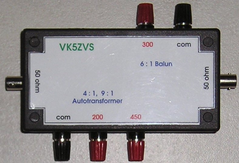
| Need a particular balun? |
| Having various baluns already made with connectors, allows for quick testing.
|
|
|
| |
|
|
| |
|
The various baluns are made with 2 x ferrite cores,
Jaycar LF1258 taped together to form a figure eight core (side view). The wire used
is from Category 5 data cable. The type of wire provides good insulation between wires
and allows the correct amount of interwinding capacitance between the turns to give us the desired
response characteristics we're looking for in a balun.
More details to follow .......
|
|
|
| |
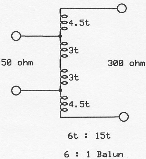
| 6 to 1 balun. |
| This balun was made with two ferrite cores,
(Jaycar LF1258)wired using Cat 5 UTP wire. The winding ratio is 6 turns to 15 turns.
50 ohm primary is 6 turns. The 300 ohm secondary is formed by adding 4.5 turns to either end of the primary,
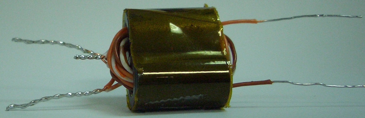
giving 15 turns overall. The picture here shows the balun core ready for testing. The two single
wires are the 300 ohm secondary. The two twisted & soldered pairs are the 50 ohm primary. The
small twisted and soldered pair is the centre tap.
|
|
|
| |
|
|
| |
|
|
| |
|
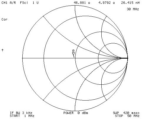
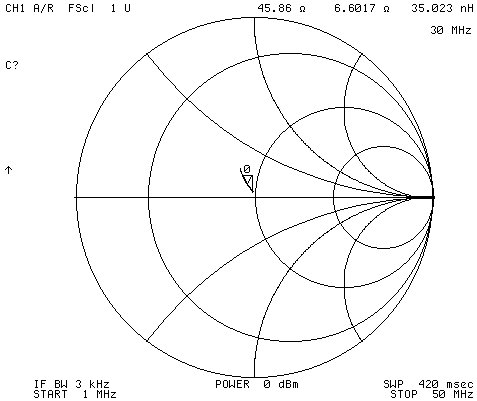
| Here's the Smith chart showing the impedance from 1 to 50MHz.
The marker is at 30MHz.
|
|
|
| |
|
|
| |
|
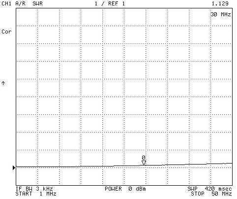
| Here's the VSWR from 1 to 50MHz.
The marker is at 30MHz.
|
|
|
| |
|
|
| |
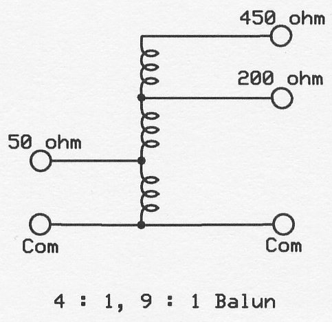
| 4:1 and 9:1 matching balun (autotransformer). |
| This balun was made with two ferrite cores, as used previously.
It uses an autotransformer design, hence, allows multiple taps for the different required impedances.
|
|
|
| |
|
|
| |
|
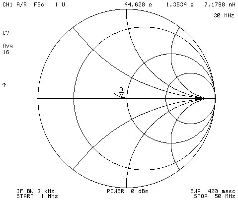
| Here's the Smith chart showing the impedance from 1 to 50MHz.
The marker is at 30MHz.
|
|
|
| |
|
|
| |
|
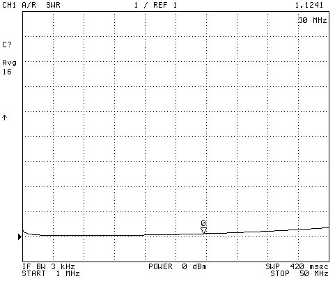
| Here's the VSWR from 1 to 50MHz.
The marker is at 30MHz.
|
|
|
| |
|
|
| |
|
| Here's the Smith chart showing the impedance from 1 to 50MHz.
The marker is at 30MHz.
|
|
|
| |
|
|
| |
|
| Here's the VSWR from 1 to 50MHz.
The marker is at 30MHz.
|
|
|
| |
|
|
| |
|
|
|