|
 |
VK5ZVS |
|
| Projects 'n' Stuff |
|
|
| Home | Back |
|
| |
| Antenna bracket for the car |
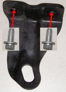
| Make use of what already exists - and remove it - save the screws!
|
|
|
| |
|
|
| |
|
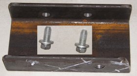
Utilising the existing screws and mounting points,
use the original bracket as a guide to mark and drill the holes in the new bracket.
|
|
|
| |
|
|
| |
|
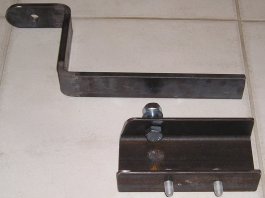
| Here we can see the new mounting tongue and the shaped bracket base.
|
|
|
| |
|
|
| |
|
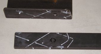
| This is the tedious bit. Mounting the base,
putting the tongue in the different positions and marking them on the pieces
for good alignment. This can happen several times - you really want to make sure
it swings the way it is supposed to!
|
|
|
| |
|
|
| |
|
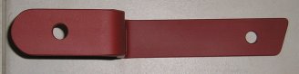
| This photo shows the
mounting tongue completed with mounting hole, the end shaped for the end stop
and painted with metal primer.
|
|
|
| |
|
|
| |
|
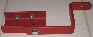
| This shows the bracket ready for some additions
and fine tuning....
|
|
|
| |
|
|
| |
|
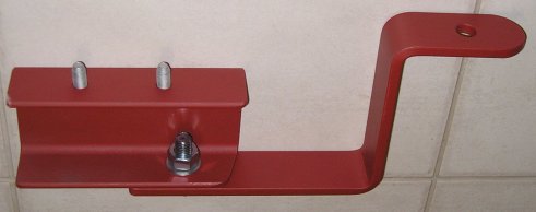
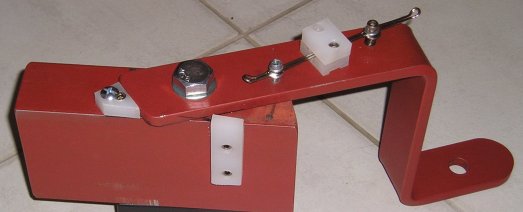
| Here's we can see the bracket from the top.
The main bolt used has 16mm diameter, and will have two nuts to secure the bolt.
One nut will be welded to the bracket and the other will provide additional
security to lock the nut and bolt so it doesn't move - once we have it in it's
final position. (We need a small amount of clearance so the tongue can swivel from
side to side.)
|
|
|
| |
|
|
| |
|
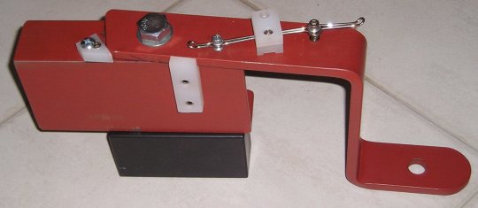
| Here's we can see the bracket upended
for clarity, so we can see the end stops and the locking pin arrangement.
End stops are used to limit travel in either direction and the locking pin
is to secure the antenna in it's travelling position.
|
|
|
| |
|
|
| |
|
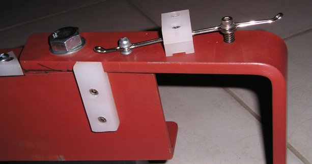
| This photo shows the travelling position -
where the tongue is against the side end stop and the hinged locking pin is
down through the tongue and base - which locks the tongue in position.
The lever is spring loaded.
|
|
|
| |
|
|
| |
|
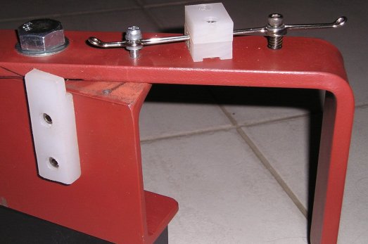
| Once the lever has been moved towards the tonge
- against the spring action - the pin is lifted out of the hole in the base,
via the plastic cantilever arragement, allowing the tongue to swing.
Here we can also see the tongue end against the end stop, limiting it's travel
in that direction.
|
|
|
| |
|
|
| |
|
| Here's a close-up showing the pin in the release position,
the spring and the lever.You may even see the bevel in the side end stop.
Most of the plastic parts will be replaced with harder wearing metal alternatives.
|
|
|
| |
|
|
| |
|
|
| |
|
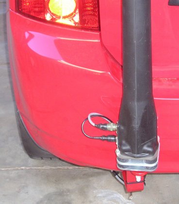
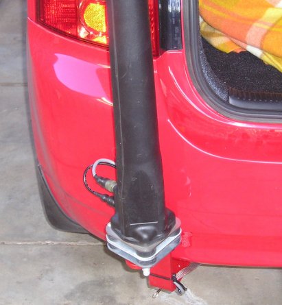
| Here's the bracket installed and in the locked position on the car
with the antenna.
|
|
|
| |
|
|
| |
|
| To move, just lift the lever
and slide the assembly to the side - out the way!
|
|
|
| |
|
|
| |
|
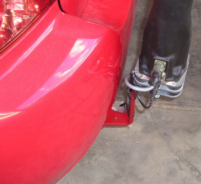
| Left side view showing clearance between antenna and bumper.
|
|
|
| |
|
|
| |
|
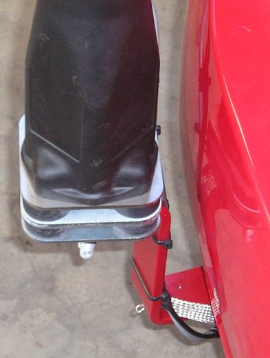
| Final view, showing the clearance from the right side.
|
|
|
| |
|
|
| |
|
|
|