| |
|
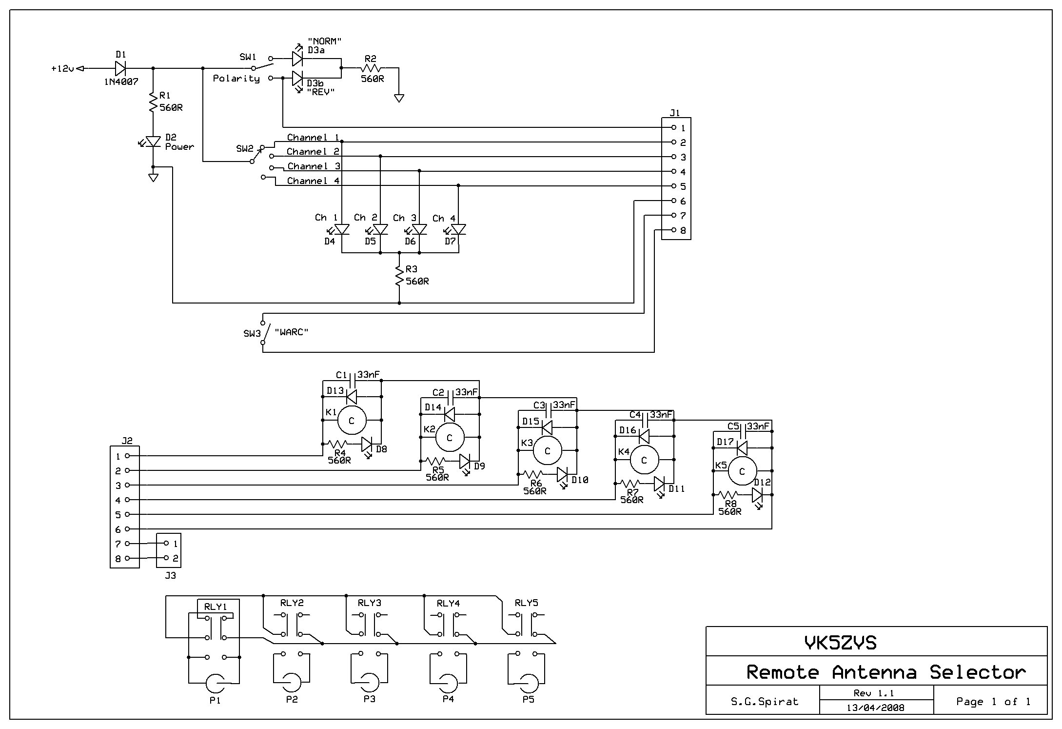
There are two parts to the remote switchbox.
The top part of the schematic shows the wiring of the control box used at the new location.
This part supplies the power for the whole circuit and a led is used to indicate that the
circuit has power. Switch 1 (SW1) is used to enable/disable a remote relay for transposing
both the inner and outer conductors on the main feedline to the antenna, at the remote end.
Switch 2 (SW2) is used to select an antenna by providing power to the relay at the remote
location and also provides power to the local antenna selector led indicator.
Switch 3 (SW3) is used to provide remote switching across the spare cable pair.
J1 is connected to a single 4 pair Cat 5 UTP cable and connects to the remote relay box via J2.
The bottom part of the schematic shows the remote relay box which provides the relays
and coaxial cable sockets for antenna cable connections. Each relay has a rf bypass capacitor,
free-wheeling diode and led indicator. When a particular relay is energised, you will be able to easily
determine which relay is active. Each relay isolates both the inner and outer conductors of the bnc sockets
from the circuit, when not energised. (i.e. both parts of the connection are isolated and floating,
with reference to ground.) A single coaxial cable runs from connecr, P1, to the new location.
|
|
|