|
 |
VK5ZVS |
|
| Projects 'n' Stuff |
|
|
| Home | Back |
|
| |
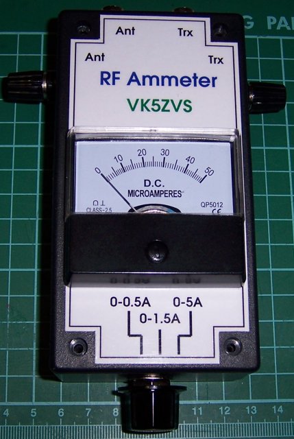
| Making another RF ammeter. |
| This project allows the measurement of rf current either via single inline
connectors or via bnc connectors on the top of the unit. I have also included a three way rotary switch
current selection for better viewable metering resolution.
|
|
|
| |
|
|
| |
|
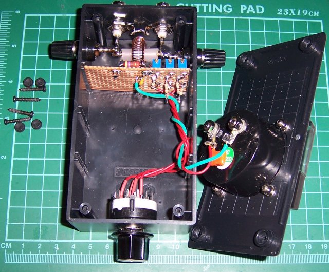
Here is an inside view of the rf ammeter.
The three 15 turn pots are used to calibrate the scaling resistors for the
50uA meter. The 40 turn current transformer can be seen, along with the 470 ohm
2 watt load resistor at the board edge.
|
|
|
| |
|
|
| |
|
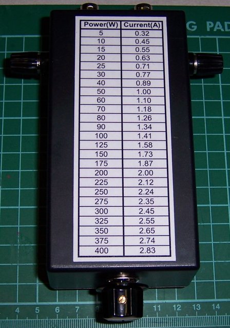
I've included a lookup table for the rf current values
for when the ammeter is connected to a 50 ohm load for various power levels.
|
|
|
| |
|
|
| |
|
The schematic shows a typical current transformer arrangement used in the
detection and metering of rf currents. This unit uses a small toroid (Jaycar LO1230) wound with 40 turns of
0.5mm ECC wire (Jaycar WW4016) and terminates into a 470 ohm 2 watt metal film resistor (Aztronics PRO2/470R).
A small signal silicon diode (1N4148) is used to rectify the ac signal and smoothed with a 100nF monolithic
capacitor, to provide the required dc current for the 50uA meter (Jaycar QP5012). Additional rf bypassing is
achieved by placing another capacitor directly across the meter's terminals. The scaling resistors
consist of 3 x 100k ohm 15 turn trimpots (Rockby #12639) and additional fixed carbon resistors connected to form
the three series scaling resistors, connected to a common point. The appropriate scaling resistor is then selected
via a three position rotary switch (Jaycar SR1216). The circuit is built on a small piece of veroboard and put
into a UB3 style jiffy box (Jaycar HB6013). The scaling resistors are approximately 150k for 0 to 0.5A, 483k for
1.5A and 1M53 for 5A FSD.
|
|
|
| |
|
|
| |
|
|
|