|
 |
VK5ZVS |
|
| Projects 'n' Stuff |
|
|
| Home | Back |
|
| |
| 80m end fed half wave tuner. |
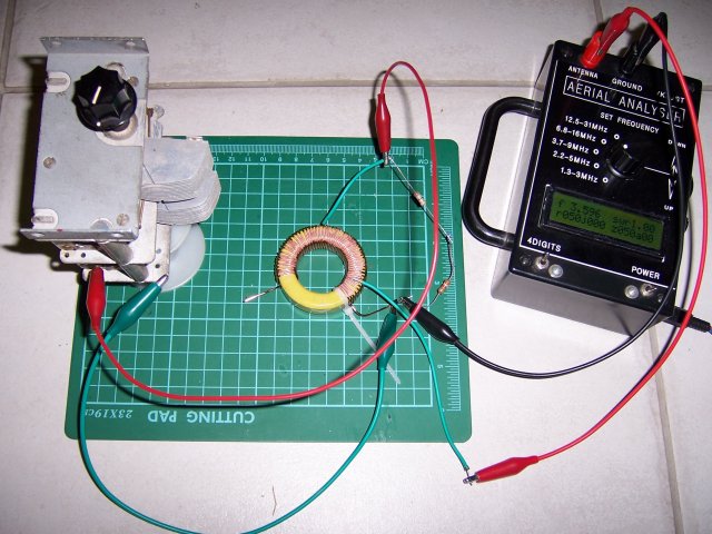
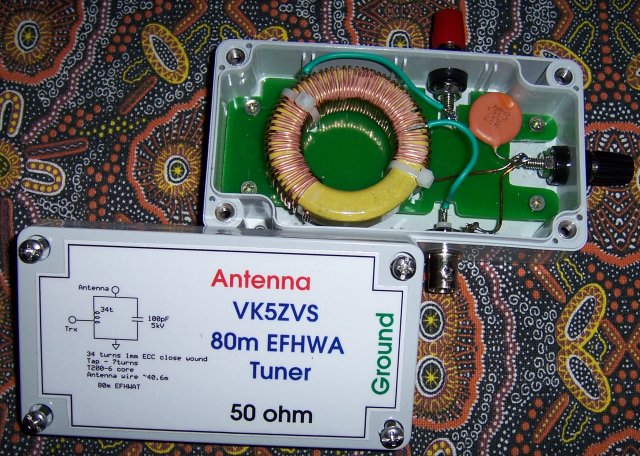
| The design for this project is of a similar nature as used for the previously constructed 160m and 40m tuners.
The design layout shown in this photo shows the tuner components connected to a resistive load and the antenna analyser to give the desired results.
The resistive load was determined by using the TuneHalf.exe program. The variable air spaced capacitor is used to tune the circuit to resonance and
the antenna analyser is used to confirm both the tap point for best return loss and the point of resonance.
|
|
|
| |
|
|
| |
|
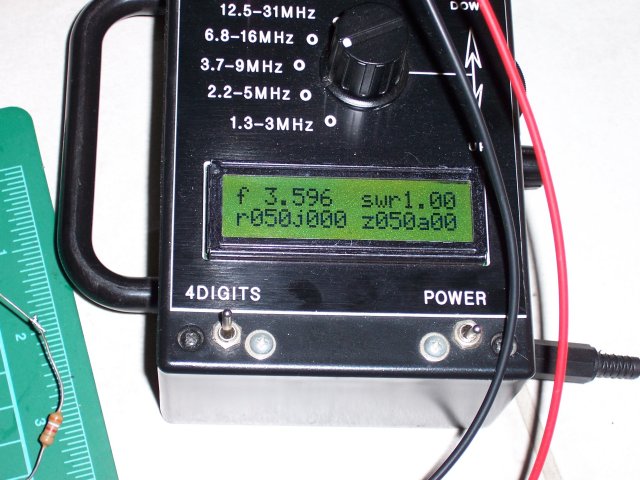
Here is the display of the analyser giving the vswr reading of 1.00:1
at a frequency of 3.596MHz. The impedance is 50 ohms resistive with no reactive components, which is
expected with a carbon resistive load.
|
|
|
| |
|
|
| |
|
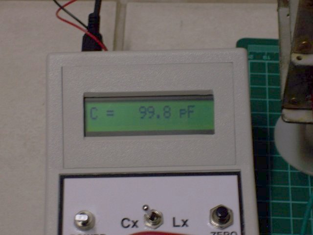
Using the LC meter, here is the value of the air spaced capacitor (separated from
the circuit!).
|
|
|
| |
|
|
| |
|
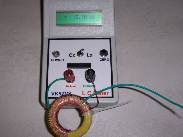
Using the LC meter, here is the inductance value of the winding on the toroid core (separated from
the circuit!). The green wire is the 50 ohm tap point (which is left un-terminated for this test). You may be wondering why I haven't
spaced the windings out more or why there are extra turns. The reason for this is that this core was also being used in a multi-band
design - which is still under experimentation.
|
|
|
| |
|
|
| |
|
Here's the view of the label attached to the cover and the bits
installed in the box.
|
|
|
| |
|
|
| |
|
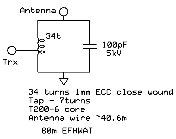
Here's the schematic of the tuner. Note that the windings for this tuner are close wound.
This will affect the overall inductance and the 50 ohm tap point.
|
|
|
| |
|
|
| |
|
|
|